
Battery Power in a Salvage Economy
Here at Green Wizards we like to promote a "Renascence man (or woman)" style of learning, where you don't be a specialist know one subject well, but a generalist, knowing many subjects half way well. There was a time in American culture where blue collar workers, could and did discuss in the public square all sorts of important subjects.
One such Green Wizard is the gentleman who goes by the name of "Sweet Tatorman". If you've visited our forums, you will often see him sharing his plant, farm and garden knowledge. He knows much more and sent me this detailed discussion on battery tech.
Enjoy and learn...
---
Battery Power in a Salvage Economy by Sweet Tatorman
Over the years I have given quite a bit of thought as well as performed hands on experiments on the matter of rechargeable battery power in a savage economy. In this post I will discuss what is available should the grid go down long term with a focus on low power usage such as LED lighting and low power electronics. My focus is not on large storage capacity arrangements such as a fully capable system sized for refrigerator/freezer/microwave oven etc. I will discuss available battery types and the characteristics and utilization of each type. Implicit in much of the discussion is that the charging means will be via solar panels.
Up until a couple of years ago I was considering only 12V lead-acid (Lb-acid) automotive batteries and small Lithium-ion (Li-ion) batteries of the type found in various consumer electronics and cordless power tools. My rational was/is that both types are readily at hand for everybody. A couple of years ago I broadened my focus to include hybrid, plug-in hybrid, and full EV autos. Previously I had ignored these but I received a request from an in-law mechanic to develop testing methodology for evaluating batteries in hybrid autos suitable for non-dealership mechanics with limited resources. Fulfilling that request necessitated a close look at the state of hybrid auto battery technology leading to the conclusion that hybrid/plug-in hybrid/full EV autos should also be viewed as a battery resource.
A brief description of how the battery in a regular (not plug-in) hybrid operates is in order.
These batteries have a rather modest energy storage capacity typically in the range of 1000-2000 Whr. By way of comparison, a typical Lb-acid 12V auto battery has a capacity on the order of 800 Whr. In practice the full capacity of either is not used. Even though the hybrid battery has only about twice the capacity of a regular 12V Lb-acid auto battery it's replacement cost at a dealership is on the order of $4000-$6000 vs that of a regular Lb-acid auto battery at less than $100. Clearly manufacturers of hybrid autos must deliver long battery life least they incur the wrath of consumers.
As used, a hybrid auto battery cycles through only a fraction of it's total capacity typically centered on 50% State of Charge (SOC). For example, the battery will be allowed to discharge to 30% SOC before being charged by the engine up to 70% SOC. The low and high SOC points vary with make and model but are always well away from 0 and 100%. Charging also occurs during braking where a portion of the kinetic energy is recovered as electric energy. Thus in stop and go city driving 100's of shallow charge/discharge cycles can occur in a days driving.
Consider service as a taxi in NY city. A fleet of Ford Escape Hybrids (manufactured 2005-2009 model years) were employed as taxis and reportedly original batteries lasted up to 300,000 miles. This would imply 100's of thousands of charge/discharge cycles. The relevance of high cycle count is that re-purposed for off-grid use this is desirable. Cycled once a day = 365 cycles per year, so in 30 years 30 X 365 = 10,950 cycles. I believe that with proper management of operating conditions that this long life is likely achievable with two battery chemistries. Lb-acid is not among them.
I suspect that most folks will be skeptical of the idea of rechargeable batteries lasting 30 years given their personal experience of replacing their auto batteries every 4-5 years as well as phone or laptop batteries going South in 3-4 years. The key to long life is selecting the right battery chemistry and careful attention to operating conditions. While it is possible to design a Lb-acid battery with a 20 year life attainable these are different in design from a 12V auto battery. The later is what will be available in quantity in a salvage economy scenario. For these at best around 5 years of daily cycling is attainable ( I have accomplished this myself) with shallow cycling using only the top 10-20% of SOC and careful charge management.
As noted above, the energy content of a hybrid battery is small. Through the SOC range it is normally operated it can only propel the auto about one mile without the assistance of the engine. A Plug-in hybrid works similarly to a regular hybrid but is equipped with a much larger battery which enables the option of 20-40 miles of driving using only battery power. A full EV has yet a larger battery and dispenses with the internal combustion engine (ICE) altogether. When hybrids were first marketed the only battery technology which could support the required very high charge/discharge power using a relatively small battery was Nickel-Metal Hydride (NiMh). With later further maturation of Li-ion they became an alternate viable option for use. To date, the majority of regular hybrids sold use NiMh but in the future NiMh will likely be largely supplanted by Li-ion. AFAIK, all plug-in hybrids and full EVs use Li-ion. Either of these battery chemistries have the potential for >20 years of daily cycling. Successful use in hybrid autos supports the case for NiMh.
For the case of Li-ion, convincing experience by NASA supports the expectation of long life. Li-ion batteries are widely used in satellites. A satellite in low earth equatorial orbit has an orbital period of ~90 minutes, half illuminated and half in the earth's shadow. The battery thus experiences 16 charge/discharge cycles per day. Some Li-ion equipped satellites have accumulated over 100,000 cycles. That is over 17 years at 16 cycles per day.
Remember that Mars rover that was designed for 90 days operation yet managed to crawl around for 14 years? You guessed it, Li-ion batteries. It wasn't the batteries that finally ended the mission. It is believed that excessive accumulation of dust on the solar panels preventing adequate charging was the final cause of demise. You might think that NASA can buy fancy special specification batteries and in some cases you would be correct. Increasingly, NASA and other satellite designers are using "COTS" cells. COTS is an acronym used by NASA for Commercial Off The Shelf. In other words, there may be a satellite passing overhead at this moment that uses the same make and model cells as you have in some consumer item that you own. I'll supply a link towards the end of this post for those who wish to get deep into the technical details of Li-ion battery use in spacecraft.
So why do your rechargeable NiMh AA cells or your Li-ion cell phone battery crap out in 3-4 years when a hybrid auto or a Mars rover is still going strong after a decade? It is all about managing a number of parameters associated with charging and discharging. The most important of these are the limits placed on minimum % SOC during discharge and maximum % SOC during charge. Data on the relationship of these two limits on the attainable cycle life of NiMh is hard to come by but following the general practice of hybrid auto designs is a reasonable guide. For Li-ion there is a large body of data on the relationship between charge termination voltage (which determines final SOC) and cycle life.
A general rule of thumb is that for each 0.10V reduction in final voltage the attainable cycle life will double. Li-ion cells in consumer items are typically charged to 4.20V. Were this to be reduced to 4.00V (i.e., 2X a 0.10V reduction) 4X cycle life would be attainable. This comes at the expense of energy stored per charge, in this example 75-80% at 4.00V vs 100% at 4.20V. If you are in it for the long haul, having 4X at 80% is much preferable to 1X at 100%. This relationship is only good down to ~3.90V at which point other degradation mechanisms begin to dominate cycle life. FWIW, the Li-ion batteries on the International Space Station use a final value of 3.95V for the batteries used to power the station. Data on the relationship between the lower % SOC upon discharge and cycle life is harder to come by. Here using the example of plug-in hybrid and EV autos suggests that 3.5V/cell which corresponds to ~20% SOC is a reasonable choice.
Other factors known to affect cycle life of all types of rechargeable batteries are temperature and rate of charging and discharging. For all three of the battery types under discussion, Lb-acid, NiMh, and Li-ion, higher temperatures lead to shorter life. A rough rule of thumb is that for each 10C increase in temperature the life will be halved. Longest life can be expected below room temperature but above 0 C (32 F). Li-ion in particular is subject to detrimental effects if charged below 0 C (32 F) though low charge rates of C/10 or less are likely of little consequence down to -5 C (23 F). Some manufacturers of Li-ion cells recommend reducing charging current between 0 and 10 C (32 & 50 F) with C/4 maximum typical. As used herein, the expression of charge and discharge rates as C/X is a convention whereby C=capacity in Ahr and X is the time in hours to discharge that capacity.
For example for a battery with a capacity, C, of 10 Ahr a discharge rate of 1A would be expressed as a rate of C/10. In general charging rates in an off-grid situation are sufficiently low that the deleterious effects of high charge rates will not be a consideration. All three of the battery types under consideration can support high rates of discharge. At the rates that would be typical of powering LED lighting and low power electronics consideration of discharge rate on cycle life can also be ignored. Below I will discuss the characteristics of each of the three battery chemistries that will be widely available in a salvage economy.
First to be considered are the Lb-acid batteries in the widely available form of automotive batteries. These are designed to be capable of supplying high power (several kW) for brief periods to enable starting the engine. The physical design of the battery that enables this also makes the battery unsuitable for deep cycling service. Only a dozen or two of 100% discharge cycles and these batteries are trashed. If only the top 10-20% of capacity is used in the charge/discharge cycle up to ~5 years of daily cycling is attainable. KEY POINT, unlike NiMh and Li-ion batteries, Lb-acid batteries do not benefit from limiting SOC to less than 100%. The opposite is true. The more time a Lb-acid spends in a SOC less than 100% the greater the accumulated deterioration. I will not discuss in detail charging protocols for Lb-acid batteries as this information is widely available on the web. Just a few comments on the subject of charging. Except for the case of relatively low charging currents some form of charge controller is required.
Automotive batteries come in two varieties; so called "maintenance free" where there is no means to add water to the electrolyte and conventional "flooded" where there is access to each cell to view electrolyte level and add water to make up for that lost during overcharge. This ability to add make up water makes the conventional flooded battery more desirable as it is more resistant to damage from overcharge. A charge controller failure resulting in overcharge that goes undetected for a period of time long enough to be sufficient to damage a "maintenance free" battery may require no more than the addition of water to a conventional flooded battery. All else being equal, a properly maintained flooded battery can be expected to last longer than "maintenance free" types.
As stated earlier, to get long cycle life from automotive batteries it is necessary to limit each discharge to the top 10-20% of capacity. This can be done by either by manually monitoring battery voltage and ceasing discharge at an appropriate level or by providing circuitry that automatically does the same. This approach is complicated by the fact that "appropriate level" varies with the load. Heavier loads will pull the battery terminal voltage down to a lower level for the same SOC than a lesser load. Assuming low loads only, such as LED lighting and/or low power electronics a lower limit to battery voltage in the range 12.60V to 12.50V is appropriate. The lower value the greater the % capacity used but at the expense of lower cycle life.
These values should be compensated for temperature at the rate of 6mV/C. Note that this is a much lower temperature coefficient and positive than that associated with charging voltage which is negative. Low voltage discharge circuitry is fairly simple and straight forward for anyone even modestly skilled in circuit design. If using an off the shelf solar charge/discharge controller, with a few exceptions most low cost ones lack the ability to set the low voltage disconnect value at an acceptably high value for use with automotive batteries. These typically have a fixed very low cutoff voltage in the range of 10.0 to 11.0V which is even undesirably low for batteries designed for deep cycling service. If using one of these low cost controllers it will be necessary to provide additional means to limit discharge to an acceptably high level of SOC. It should be noted that the IN/OUT energy efficiency of Lb-acid batteries is fairly poor when operated in the upper portion of their SOC range. This can be a major consideration if available charging means are limited and alternate battery options are available.
Next to be considered are Li-ion batteries. As noted earlier these are widely in use. It is the rare household that doesn't have them powering some item. They excel as a rechargeable power source in the following regards: IN/OUT energy efficiency is very high, >95%, at moderate charge/discharge rates; high cycle and calendar life is attainable; extremely low rate of self discharge; can be stored for long periods in a partial SOC without harm unlike Lb-acid. Properly designed charge/discharge control is essential. Unlike Lb-acid and NiMh where the risk is limited to ruining the battery, Li-ion present a very real risk of fire if subjected to charging or discharging abuse. Even a properly designed system can be a single component failure away from a fire. A prudent approach would be to locate the battery in a non-flammable container on a non-flammable surface away from anything combustible.
If used as a battery of several cells in series, the need to keep all cells in the series string balanced with respect to SOC needs to be considered. At characteristic of both Lb-acid and NiMh cells it that the charging becomes increasingly less efficient as SOC increases. This causes a series string of either to be inherently self balancing. This is not the case for Li-ion. Even slight differences in individual cell self discharge rates or drain due to attached cell monitoring circuitry will cause the cells in the battery to drift out of balance over long periods of time. This need for balancing can be addressed in several ways.
Manual monitoring and re-balancing can be performed as a periodic maintenance activity. Alternately, balancing can be automated by shunting a portion of the charging current around each cell as it approaches or slightly exceeds the desired fully charged voltage. Circuitry to accomplish this is straight forward. Alternately, the need for balancing can be obviated by avoiding the use of a series string. Cells may be paralleled but this limits the battery to the voltage of a single cell, ~3.7V, which is low for most uses. A step-up switching regulator would be employed to raise the voltage to the desired level. Such an arrangement is suitable for total loads up to the 5-10W range but beyond this it becomes increasingly difficult to maintain good conversion efficiencies.
In harvesting Li-ion cells for alternate use it is important to measure the "as found" voltage. Any found to be below 2.0V should be treated with extreme caution. These may accept a charge and function normally but may have incurred hidden damage that increases the likelihood of future spontaneous combustion even if not subjected to further abuse. Assembled battery packs typically incorporate protective circuitry that disconnects the cells from the pack output terminals when the cell voltages reach the designed low voltage cutoff. The pack thus can read zero voltage at the terminals yet the cells will be found to be fine once the pack is disassembled and the individual cells accessed for measurement. It should be noted here that the protective circuitry incorporated in Li-ion packs places a small but continuous drain on the cells. It is possible to design this circuitry to draw such low current that the pack could be left unused many years before the cells would be drained to the point of damage.
It is my observation, however, that some pack designers are so slack in this regard that the protective circuitry draws enough current that the pack would be ruined in two years time were it to go uncharged for that period. The point here is that if a battery pack is going to eventually be used as a cell donor, it should be opened, cells verified to not be over discharged, and all circuitry connected to the cells disconnected. With the residual drain of the protective circuitry removed the cells can be stored for many years without excessively self discharging provided that the storage temperatures are not excessively high.
Li-ion cells have a nominal midpoint of discharge voltage of ~3.7V. Maximum voltage is that selected as the charging cutoff voltage which is typically 4.20V in consumer items but must be selected lower as previously discussed if long life is the objective. 4.00 to 4.05V would be a reasonable choice for a long life application. It is unlikely that you will find an off the shelf solution for charge/discharge control that provides the charge and discharge set points needed for attaining long cycle life. You will be on your own to design and build.
Listed below are the typical capacities of individual Li-ion cells from various consumer items.
- Laptops and tablets with cylindrical cells: 2-3Ahr
- Laptops and tablets with rectangular cells: 3-10 Ahr
- Cell phone (smart): 3-5Ahr
- Cordless hand power tools with cylindrical cells: 1.5-3Ahr
- Hybrid auto with rectangular cells: 5-6Ahr
- Plug-in hybrid with rectangular cells: 20-25Ahr
Last to be considered are NiMh batteries of the type used in hybrid autos. Of battery using non-conventional autos; i.e., hybrids, plug-in hybrids, and full EV, hybrids are by far the most numerous with over 4 million on the road in the US by 2020. Of these 4 million, over 2 million are Toyota Prius models or other models which use the same battery module as the Prius. All hybrid NiMh batteries are assembled from modules each of which contain from 5 to 8 cells. The majority of models including the Prius use modules comprised of 6 rectangular cells. Several Lexus models use modules of 8 rectangular cells. The Ford Escape and Fusion hybrids use modules of 5 cylindrical "D" cells assembled into module "sticks". Several Honda model modules are similar except that the sticks are comprised of 6 cells. In all cases, individual cells within a module are not accessible. Only the ends of the series string are accessible
In assembling several of these modules into a multi-module battery the resulting voltage thus will be an integer multiple of the individual module voltage. Taking the nominal NiMh cell voltage as 1.25V, a 5 cell module would be a nominal (1.25)(5) = 6.25V and a 6 cell module (1.25)(6) = 7.50V. A series string of two 5 cell modules would be ideal for a nominal 12V system as (2)(6.25) = 12.5V. Unfortunately these will be relatively rare as only ~300K vehicles used them and they were last used in the 2012 model year. A series string of two of the much more common 6 cell modules would be a nominal (2)(7.50) = 15.0V but one must consider the maximum voltage under charging conditions which can be 1.40V/cell or even a bit higher. (12)(1.40) = 16.80V which may be excessive for some nominal 12V loads. It may be necessary to use only one module with a step-up switching regulator or a two module series battery with a step-down switching regulator to maintain voltage within the needed range of a high voltage intolerant nominal 12V load.
To attain long cycle and calendar life charge and discharge control is required. The discharge part is easy. Set the low voltage cutoff at an appropriate value, I suggest 1.15V/cell for low drain applications of C/10 or less. So for example a 10 cell series battery would terminate discharge at (10)(1.15) = 11.5V. Charging consistently to a partial SOC is not easy. I am yet to see any manufacturers' guidance on doing this. Similarly there is not much to be found in the open literature that does not require real time computation using complicated algorithms with multiple data inputs. Hybrid autos successfully operate in a limited SOC range usually centered on 50% SOC aided by what are proprietary algorithms operating upon various real-time data as well as stored data of multiple recent and longer term monitored variable values. This level of sophistication is simply not available to those needing an expedient home brew solution. After over a year of looking at this problem of reliably attaining a partial SOC of NiMh batteries where there is variable discharge between charges and variable available charging as is the case with solar charging, I have found only less than satisfactory solutions that differ somewhat in there degree of badness.
The first bad solution to be considered is really not a solution at all if the problem is defined as reliably attaining a desired % partial SOC. Unlike Li-ion which are absolutely intolerant of continued charging beyond 100% SOC (grab the fire extinguisher!), both Lb-acid and NiMh have electro chemical mechanisms to accommodate some degree of overcharge. Lb-acid batteries in fact require it to some degree to maintain battery health. NiMh do not benefit from overcharge. Even at low "trickle charge" rates some deterioration can occur. That said, most manufacturers say a continuous trickle charge of C/40 or less is permissible though not encouraged. The (non) solution proposed here is to limit the maximum available charging current to C/40 or less.
Assuming that solar panels are the charging source, if the panel maximum output is C/40 then it is possible to operate with no charge control at all. The drawback to this arrangement is that for low insolation climates (with limited sunlight) or the time of year it would be necessary to have large battery capacity to store useful amounts of energy while maintaining a panel array to battery size ratio such that the maximum charge current rate of C/40 is not exceeded. Even in my relatively sunny climate I can expect several 5 day periods each Winter in which the average solar insolation is less than the equivalent of 1 full sun hour per day.
An improvement on this bad solution is to increase the solar array size but limit the current output to the C/40 rate. This can be accomplished by means of either a linear or switching regulator. By this means the C/40 rate can be maintained at insolation less than full sun levels. If desired, to minimize the frequency at which the battery reaches fully charged, the charging rate could be seasonally adjusted below the C/40 rate during the higher insolation portions of the year. The larger than C/40 array also permits the following capability. In the event the battery reaches it's low voltage cutoff and assuming that the approximate capacity of the battery is known, the charging current can be raised or the current limiting device bypassed altogether to fast charge for a period of time provided that this is terminated before reaching fully charged. Termination can be performed manually of via a timing device.
The next bad solution to be considered is current limited constant voltage charging as is typically used for Li-ion. All available literature says that this is unsuited for NiMh. Implicit in the literature is the assumption of the need to charge to 100% SOC. What about the case of desiring to attain less that 100% SOC? After considerable experimentation I have concluded that is not practical in a grid down environment. The appropriate charging voltage is much too temperature sensitive. It can be made to work if the specific battery has been well characterized and the temperature tightly controlled. Tight temperature control is unlikely to be achievable in a grid down environment.
The last solution to be considered is the best of the bad lot. To aid in making sense I will first digress and discuss what is happening with the cell electro chemistry as it reaches higher % 's of SOC. For a NiMh cell cycled from 0% to 100% SOC then discharged from 100% back to 0% SOC energy efficiency is not particularly good with 66% being a commonly cited value. In the range of 0-70% SOC, however, the efficiency is extremely good approaching that of Li-ion. In this range while charging, almost 100% of the charging current drives the electro chemistry that actually charges the cell.
Starting in the 70-80% SOC range an increasing fraction of the charging current does not serve to charge the cell but instead generates oxygen at the positive electrode. The resulting O2 molecule dissolves in the electrolyte. Because it is a neutral molecule it is mobile only due to the mechanism of diffusion and is not driven by the voltage difference between the two electrodes. Generation of this O2 causes the internal pressure of the cell to rise which if sustained would eventually cause the cell to rupture or vent if there were no means to remove the O2. There is a mechanism to remove the O2. Once an O2 molecule encounters the negative electrode it can enter into one of two possible reactions with hydrogen there. The end product of these two reactions are H2O and -OH. The actual reactions that serve to charge the cell are exothermic but only slightly so. For the reactions that generate the O2 followed by its removal all of the associated energy is converted to heat. This will cause the cell temperature to rise. Once the cell temperature is above ambient it will also be dissipating heat to the environment. The degree of temperature difference between the cell and environment will thus be dependent in part on the rate of O2 generation and removal.
As % SOC continues to increase ever greater fractions of the charging current is diverted to O2 generation and decreasing fractions to actual charging. This suggests a viable method of charge termination prior to reaching 100% SOC. As stated earlier the onset of the O2 generation reaction is in the range of 70-80% SOC. It will tend to be in the lower end of this range at higher rates of charge and the upper end at lower rates of charge. If cell temperature is monitored and compared to the environment a charge termination can be based upon a fixed differential temperature. Such a scheme of charge termination is relatively easy to implement through the use of thermistors and a comparitor. For this scheme ambient or battery temperature is not relevant, what is relevant is the difference between the two. Thermistors are resistors whose resistance varies with temperature. Most commonly employed are those of the variety with a negative temperature coefficient (NTC) which simply means that the resistance decreases with increasing temperature.
The formula for relating the resistances at two different temperatures is nonlinear and beyond the scope of this discussion here except as follows. The formula contains a constant known as the "B" value which may be thought of as a measure to sensitivity of resistance to temperature. NTC thermistors are manufactured with B values in the range of 3100-4500 with values of 3900-4000 most common. While the relationship of resistance to temperature is nonlinear, the ratio of resistances represented by a change of 1 degree will be nearly constant over a modest range of temperatures. This is just the characteristic needed if we are interested in the difference in two temperatures, in this case ambient and battery.
Take for example two thermistors with a B value of 3900 and the nominal value of 10K ohms. Nominal values are typically specified at 25C. One will monitor ambient and the other battery temperature. If both temperatures are the same, their resistances are the same and thus the ratio is 1.000. Now consider three different pairs of temperature presenting 1 degree C difference and take the ratio of the resulting resistances with the lower temperature (higher resistance) in the numerator. For 10C/11C the ratio is 1.044, for 20C/21C the ratio is 1.041, for 31C/30C the ratio is 1.039. While the three ratios are not exactly equal they are close enough for the task.
Now suppose we want to terminate the charging when the battery temperature rises 1 degree C above ambient. Simply form a voltage divider from the two thermistors and feed this into one input of a comparitor. The other input of the comparitor is fed by a voltage divider of fixed value resistors with a ratio of 1.04. The comparitor thus changes state when the thermistor ratio rises to 1.04. To prevent dithering at the transition point as well as to insure that the charging remains off for awhile it is necessary to add some hysteresis to the transition setpoint by adding a resistor from the comparitor output to the input with the fixed value resistor divider. It would not be appropriate to route the hysteresis resistor to the input with the thermistor divider as the amount of the hysteresis would become variable with absolute temperature. In the example under discussion an appropriate value of hysteresis would be ~0.5C so the value of the hysteresis resistor would be selected to cause the reset at a thermistor resistance ratio of 1.02. In this example if the comparitor output "low" is to be "charge off" as would be the case of using the comparitor output to drive the gate of an N-ch MOSFET as the switching element, then the thermistor divider would be connected to the comparitor (-) input and the fixed value divider to the (+) input.
Experimentation has shown that having the charging remain off long enough is the main concern not remaining off too long. Should the comparitor terminate the charging early in the day (solar charging assumed here) it is possible that the comparitor would reset and trip several times, each time charging the battery with another small increment of % SOC. This scheme of charge termination is thus rather imprecise in attaining a consistent SOC. This can be addressed to some degree at the expense of added complexity to what was initially a very simple scheme. Some form of lockout could be provided whereby the charging is inhibited for a period of time such as 10 hours. This would be a good application of a timer IC.
I have tested this general scheme in the simple form (i.e., with lockout timer) using a single 5 cell module suspended horizontally in free air in a still air and temperature stable environment. Since this is a single module test, air can freely circulate over it's entire surface without adjoining modules inhibiting airflow as would be the case in a multi-module assembly. This single module test can be seen as the best case for module to air heat transfer in a still air temperature stable environment. Using a constant C/10 charge rate a fairly consistent termination using a 1 degree C rise occurs in the 80-90% SOC range. While not tested, it appears that the delta 1C termination criterion could be met for lower charge rates down to C/20. While 80-90% SOC termination is likely higher than optimum it certainly is greatly superior to 100% SOC cycling.
Unfortunately, if several more cooldown/reset/charge/trip cycles are permitted to occur close to 100% SOC will be reached. It was noted that after charge termination the module temperature will continue to rise ~1C before falling back to the value at which the trip occurred. This can be understood by considering that the O2 generated at the positive electrode reaches the negative electrode by the leasurely process of diffusion and it is at the negative electrode that the two reactions that remove the O2 releases as heat the energy embodied in the O2 creation. In effect, this introduces some electrochemical hysteresis to trip and reset in addition to that engineered into the comparitor trip and reset values. Using the 1C and 0.5C trip and reset values the addition of the electrochemical hysteresis yields an overall delay on the order of 2-3 hours from trip to reset. This suggests the benefit of adding some scheme of timed lockout to avoid several trip and reset cycles in a single solar day.
What can go wrong with the above scheme? Plenty, actually. In a grid down scenario it is unlikely that the battery can be located in a constant temperature environment. It can be expected that battery temperature will follow the diurnal temperature swings with some time lag and hopefully somewhat muted in the high to low swing. In the typical pattern of cooling nights and warming days the battery temperature is having to chase the ambient temperature upwards during the day thus at least delaying if not preventing altogether the charging termination based upon battery temperature rising above ambient. Conversely, in the case of a reversal of the typical diurnal temperature pattern, should a cold front move in early in the day, ambient will fall below battery temperature terminating charging, possibly even before it gets started. How large a rate of change in ambient temperature will torpedo this charging control scheme? I lack the ambition to investigate that question rigorously. Less rigorous observation in the course of the testing of the single module suspended in free air suggests the value may be on the order of 0.5-1.0 C/hour. This test configuration offers optimal thermal coupling to the environment. A densely configured multi-module battery would be able to accommodate an even lesser rate of change. In a below grade basement sufficiently low rates of temperature change may be attainable in some climates. In a mobile home or poorly insulated frame home I think it is unlikely.
It took me a long while to see a solution to the above problem. There is one. Rather than comparing the temperature of the battery under charge to the local ambient temperature, it instead is compared to a second identically configured battery which is not being charged serving only as a temperature reference. While it might seem wasteful to have a second complete battery serving only as a temperature reference, it can be utilized by periodically swapping the roles of the two batteries thus distributing cycles between them. Having the second battery in reserve in a charged state permits the swapping of the two in the event that the battery in use becomes fully depleted in an extended period of low insolation. As stated at the outset, all of the non-complex solutions to the problem of attaining less than 100% SOC for NiMh are less than fully satisfactory. The scheme above appears to the least bad of the lot.
Before leaving the topic of NiMh batteries a few more points. For clarity in describing the above charging scheme I have implied use of a single thermistor at each of the batteries used. In practice a series array of several thermistors is preferred. Thermistors are cheap. The use of several thermistors in each battery assembly offers several benefits. A more representative measure of temperature is attained. Additionally, prior to use each thermistor can have is value measured individually and the various thermistors can be mixed/matched to attain as nearly as practical identical values for the two series strings.
I personally have tested modules from a very limited number of vehicles. The 5 cell module which was the subject of the testing discussed above was taken from a Ford Escape Hybrid with a DOM of Dec 2005 and 167K miles. While multiple modules from that vehicle were tested (50) it was the only source for that module type. I have tested modules from 5 Toyota Prius, only one or two modules from each. In the case of two source vehicles the modules were effectively paperweights. It is probable that these modules are from vehicle batteries that went unused for a long but unknown period of time. The remaining three were found to be of varying condition but it all cases had retained a lesser % of original specified capacity than the case of the Ford Escape modules despite having later DOMs. Mileages of the Prius donor vehicles are unknown. It would appear that modules comprised of cylindrical cells of the type tested and by extention those used in the Honda hybrids hold up better over time than the rectangular modules of the Prius style. While my own data set is much too small to support this conclusion, more extensive testing by others does.
For the past 20 years the Department of Energy (DOE) has sponsored a testing program for hybrid and other alternative vehicles. The actual test program is run by the Idaho National Laboratory (INL). Test data from that program are available for a large number of tested vehicles online as downloadable pdf files. I will provide a link. This is an excellent resource to learn what type of batteries are used in various vehicles and how well their performance holds up over time.
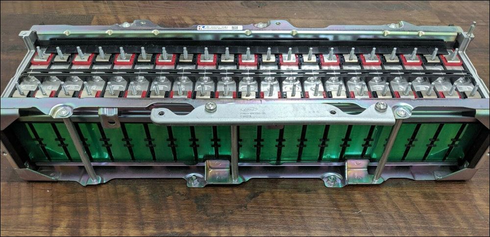
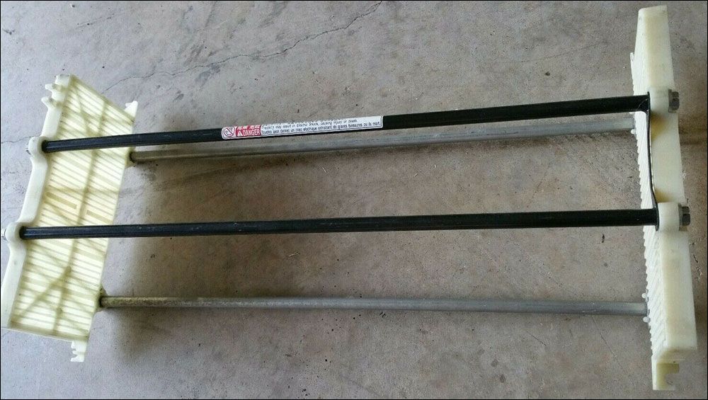
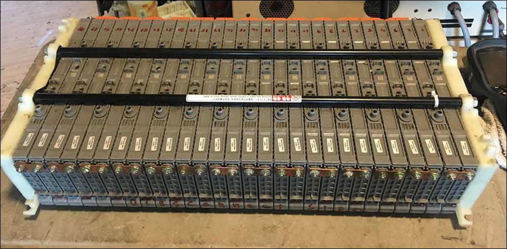
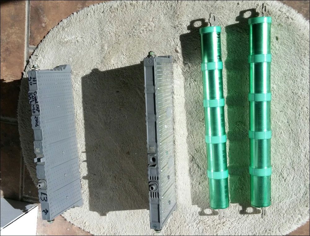
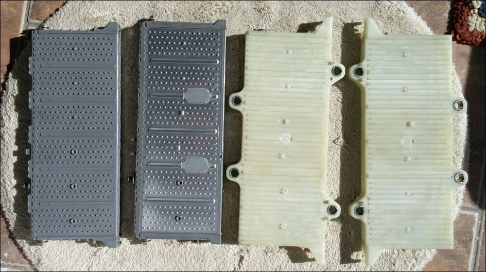
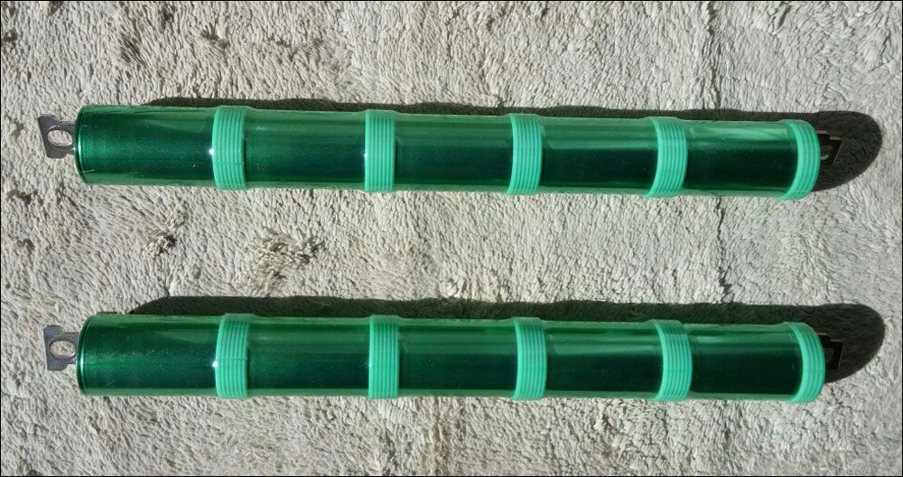
A bit more information specific to the Prius style modules which represent the major portion of NiMh hybrid vehicles on the road to this time (2020). The O2 that evolves at the positive electrode as the upper portion of the SOC range is reached causes the internal cell pressure to rise and remain elevated until all of the O2 is removed via reaction at the negative electrode. In a cylindrical cell the outer wall is a steel can with sufficient rigidity to prevent swelling under the increased internal pressure. Prius style modules have a different design. The outer cell wall is comprised of plastic of insufficient rigidity to constrain swelling. Instead, all modules are stacked horizontally side by side with rigid plates at each end connected by 4 threaded rods which hold the stack of modules in compression. Consequentially, if re-configuring modules to an alternate arrangement it is necessary to provide a means of holding the modules constrained. If you can obtain the original two end plates from the donor battery of your modules you should do so. Lacking those, an alternate means such as a couple of short pieces of 2X4 and some "all thread" rod can be devised. Charging this style module unconstrained is very likely not conducive to long life. For fun I charged a batch of junk modules unconstrained and they do indeed swell up. See photos above of the end plates used in Prius batteries as well as their configuration in a complete module stack (28 modules total for model years 2004-2015).
A final note on the Ford Escape Hybrid modules I have tested. As noted above these were taken from a vehicle with a DOM of Dec 2005 and 167K miles. The unknown DOM of the modules is likely only a month or two earlier than that of the vehicle. Each module contains 5 "D" cells manufactured by Sanyo with a specified capacity of 5.5 Ahr. I was unable to determine at what discharge rate that capacity applies. For my testing I started discharge at 2.0A reducing to 0.2A near the end of discharge which was terminated at 5.0V = 1.0V/cell. Under this testing protocol all but a few of the 50 modules tested had a capacity of greater than 5.5Ahr! The age of the modules when tested was at least 14 years. It is these data that support the conclusion that NiMh batteries are capable of very long life with proper management.
FURTHER READING
For those wishing to take a deep dive into how DOE/INL programs spend your tax dollars, the link below is the gateway into the DOE/INL Advanced Vehicle Testing program. There is much to explore here if you have the interest.
https://avt.inl.gov/
If you want to get quickly to battery information for a particular vehicle go to the link below. Select a vehicle number for a specific vehicle type under the "Battery Pack Laboratory Results".
https://avt.inl.gov/content/pubs-vehicles
NASA also spends your tax dollars and provides some useful information. For over a decade now they have sponsored an annual "Battery Workshop" as a forum for presentation of papers on the topic of batteries as relevant to aerospace applications. They generally get the presentations online within a couple of months in a downloadable format. To access go to the link below, select a year, and from the listed papers select what is of interest to you. I suggest starting with any that have Li-ion in the title as well as either "commercial" or "COTS".
https://www.nasa.gov/batteryworkshop/past-presentations
The link below is typical of what you can find there.
https://www.nasa.gov/sites/default/files/atoms/files/3-nasa_battery_work...
----
What follows is a tabulation of battery information I have run across while looking into hybrid, plug-in hybrid, and full EV autos in the course of investigating their potential for salvage economy battery sourcing. Where sales figures are listed, these are for the US market. This tabulation is by no means exhaustive.
HYBRIDS
- Toyota Prius 2001-15: NiMh by Panasonic, rectangular modules of 6 cells each with 6.5Ahr capacity and 5mm studs for electrical connection. 2001-03 contain 38 modules, 2004-15 contain 28 modules. Hybrids using similar modules include 2007-15 Toyota Camry, 2007-15 Nissan Altima, 2011-16 Lexus CT200, GMC Yukon, Chevy Tahoe, and Cadillac Escalade.
- Toyota Prius 2015-present: NiMh or Li-ion depending upon trim level. Reported to have welded connections between modules. If true, this may complicate use.
- Lexus RX400 Highlander: NiMh 8 cell rectangular modules.
- Ford Escape 2005-9 and Ford Fusion 2010-12: NiMh cylindrical cells by Sanyo in 5 cell modules with 5.5Ahr capacity and 50 modules total. Combined sales ~300K.
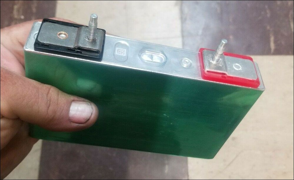
- Ford C-Max and Ford Fusion: 5.5Ahr Panasonic Li-ion rectangular cells with 5mm studs for electrical connection. Combined sales ~350K.
- Honda Civic and other models: NiMh cylindrical cells by Panasonic with 5.5Ahr capacity in 6 cell modules. Recent models use Li-ion cells with 4.7Ahr capacity.
PLUG-IN HYBRIDS
- Prius: 21.5Ahr Li-ion rectangular cells arranged in four 14 cell groups, 1.1kWh per group, 4.4 kWh total. Sales ~110K.
- Ford C-Max Energi and Ford Fusion Energi: 24Ahr Li-ion rectangular cells by Panasonic arranged in four groups of 21 cells, 84 cells total. 5mm studs for electrical connection. Combined sales ~90K.
- Chevy Volt: Li-ion ~45Ahr (variable with model year) rectangular cells by LG-Chem. Has welded connections between cells which may complicate use. Sales ~150K.
FULL EV
- Ford Focus: Li-ion by LG-Chem, 430 cells of 15 Ahr arranged in 86S/5P configuration. Conflicting available information, one source says 86 cells of 75Ahr capacity. ~10K sales.
- Nissan Leaf: Li-ion , 48 modules each with 4 cells in a 2S/2P configuration with module capacity of 66Ahr. There is much evidence that the battery pack cooling of the Leaf is inadequate causing more rapid deterioration than batteries of other vehicles. Electrical connection is by means of 6mm threaded holes. There is also a 4mm threaded hole to access the middle of the 2 cell group series string.
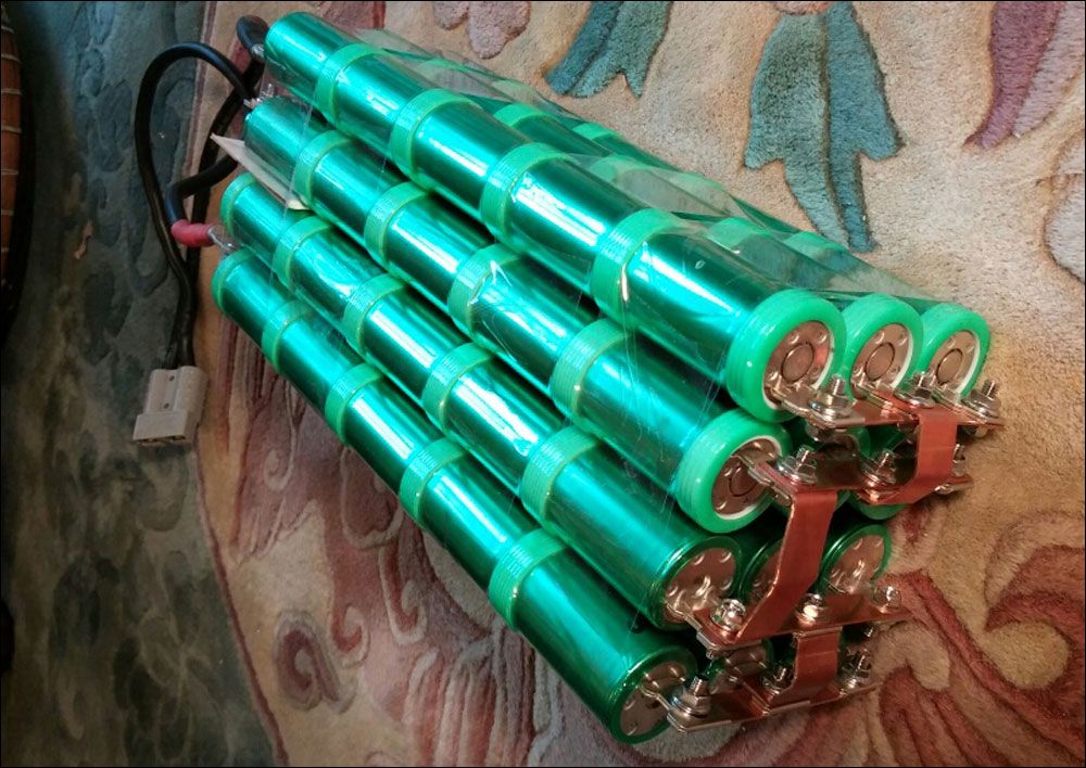
- _Tesla modules use batteries comprised of thousands of cylindrical cells that depending on model are either size 18650 which is similar to those in most laptop batteries or the slightly larger size 21700 which is used in the Model 3. The model S has a total of 6912 individual cells. Capacity of the 18650 cells is ~3Ahr and the 21700 cells ~5Ahr.
A few final comments specific to harvesting batteries from alternative vehicles. From the time the donor vehicle is last driven, or charged in the case of full EV, the battery has a finite period in which it is likely to be found in good condition. Vehicles from 50 years ago when parked and shut off had no residual drain on their batteries excepting the case of being a moron and leaving the lights on. Not so with more modern vehicles which have a host of 24/7 small loads such as keyless entry, remote starting, alarms, etc. Park the car long enough and it won't start. "Long enough" is an even shorter time with alternative vehicles. Even though they have a big 200-400V battery (traction battery) they all also have a small auxiliary 12V battery to power all the accessory items that run off of 12V in a conventional vehicle. There is no 12V starter motor. This function is handled by the traction battery and the traction motor of hybrids.
In the case of a full EV there is no ICE to be started. In all cases since the 12V battery is not required to supply the high power (several kW) to a starter motor these vehicles are equipped with smaller batteries with capacities similar to that of a mower/garden tractor battery. These alternative vehicles still have all of the small 24/7 loads as a conventional vehicle as well as a few more. In most alternative vehicles the auxiliary battery is only charged when the vehicle is running. AFAIK, none of them have a 12V alternator for charging the 12V battery. Instead a DC-DC converter is used to step down the 200-400V of the traction battery to the lower voltage of the auxiliary battery. So with a smaller 12V battery and more 24/7 vampire loads than a conventional vehicle what could go wrong? It is not uncommon for these vehicles to fail to start if left idle for even one month. The 12V battery is needed to make all the control systems work. To start up, the dead 12V battery must be jumped from another 12V source. Tesla models are the exception to only charging the 12V battery when running. Teslas have an insanely high load on the 12V battery when parked, ~30W in the case of the model S. To maintain the 12V battery charge the DC-DC converter will power up 4-6 times per 24 hours.
The point of the preceding discussion is that with a grid down scenario there is no charging, either directly in the case of EVs or indirectly for hybrids as no grid=no running gas stations=no gas=no running the ICE to charge things up. The vampire loads will still be there. Except for the case of the Tesla I do not know their magnitude but I am certain it is greater than zero. Even in the absence of load, NiMh self discharge to zero volts in ~1 year in moderate temperatures and faster at elevated temperatures. I haven't had much success with recovering much usable capacity from NiMh that have set at zero volts for an extended period of time. At least they are just junk and not dangerous. Li-ion has a negligible rate of self discharge but is potentially dangerous if overly discharged. Any cell found at less than 2V, beware. One other small detail if dealing with whole batteries. 200-400V is potentially lethal.
Exercise appropriate caution.
Comments
David Trammel
Sat, 03/21/2020 - 14:45
Permalink
Maybe We Can Get Batteries Cheaper Now That The World Is Ending
Great post, but I only understood some of it, Sweet Tatorman. I need to relearn my electrical skills that's sure.
With everything that has happened over the past two months, I don't know where civilization is headed. Will we make needed changes or desperately try to get back to the way things were, damned the consequences?
Who knows maybe we'll see a ton of old electric cars and their batteries at bankruptcy sales this Summer that we can get cheap and repurpose.
Sweet Tatorman
Sun, 05/31/2020 - 12:56
Permalink
Can you enable me to do the necessary edits to this?
David, is there a way you can enable me to do the necessary edits to this post perhaps by moving it back to the 7th circle where it started?
Sweet Tatorman
Sun, 03/22/2020 - 11:55
Permalink
A few corrections needed
David, thanks for the reformatting, it looks nicer than my original. Not surprisingly, for a reformat of this size a few things were mucked in the process. Since you have moved this to your blog vs the original circle 7 location I am not enabled to edit. I'll rely on you to take care of it. Not too many items. Listed below.
In the 4th paragraph discussing relative cost of hybrid battery vs 12V the "<$100" got dropped for the cost of the 12V battery.
In the paragraph that begins with "First to be considered are the Lb-acid batteries in the widely available form of automotive batteries. " a big block of text got dropped after the >KEYPOINT. Should read ". >KEY POINT<, unlike NiMh and Li-ion batteries, Lb-acid batteries do not benefit from limiting SOC to less than 100%. The opposite is true. The more time a Lb-acid spends in a SOC <100% the greater the accumulated deterioration. I will not discuss in detail charging protocols for Lb-acid batteries as this information is widely available on the web. Just a few comments on the subject of charging. Except for the case of relatively low charging currents some form of charge controller is required. "
In the paragraph discussing information specific to Prius style modules the rearrangement of photos requires the following change. The last sentence in the paragraph which begins "I will provide photos below of the end plates" should be modified to "See photos above of the end plates..."
In the paragraph beginning "Assuming that solar panels are the charging source, if the panel maximum output is C/40 then it is possible to operate with no charge control at all. The drawback to this arrangement is that for insolation climates" insert the word "low" in front of the word "insolation".
In the Full EV battery discussion the last sentence about Tesla batteries reading "Capacity of the 18650 cells is _3Ahr and the 21700 cells _5Ahr_" should be modified to "Capacity of the 18650 cells is ~3Ahr and the 21700 cells ~5Ahr.
Third photo in post should be rotated 90 CW.
The caption on the pair of Prius bracket photos reads "Two photos below show the Prius battery bracket". Change "below" to "above".
Thanks!
David Trammel
Tue, 06/02/2020 - 11:56
Permalink
Sent You An Email Tatorman
Check your permissions, you should be able to edit this now. Email me if you have any problems.
Sweet Tatorman
Fri, 06/05/2020 - 09:47
Permalink
I've got it all fixed except for the one photo
I've got it all fixed except for the one photo. Most of the problems in the original post apparently arose from my use of the less than and greater than symbols within the text which apparently is not compatible with HTML. I'll need your help in rotating that one photo. Thanks!